Electrical connection
Digitally switching sensors are available with a PNP, NPN or Namur output; measuring sensors come with voltage output (0 … 10 V) or current output (e.g. 4 ... 20 mA or 0...10 mA).
Connection diagrams
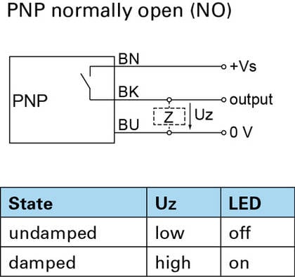
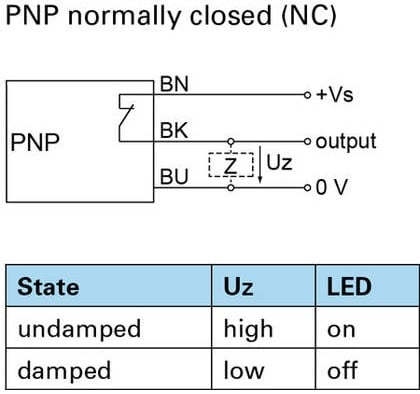
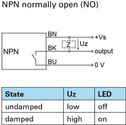
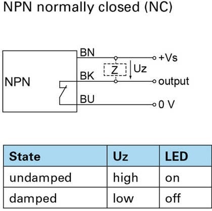
The specified diagrams indicate the undamped output. A sensor is in a damped state when an object is located in within its scanning range. In the diagrams Z denotes the typical load resistance position; Uz denotes the voltage applied to this load resistance. If Uz = high (≈ +Vs), then current flows; if Uz = low (≈ 0 V), then no current flows via the load resistance. Load resistance between output and +Vs is referred to as pull-up resistance, load resistance between output and 0 V as pull-down resistance.
PNP- or NPN output
Sensors with a PNP or NPN output have a 3-wire design (+Vs, output and 0 V) and operate with direct current (DC). The load resistance of PNP sensors is between output and 0 V (pull-down resistance), while load resistance of NPN sensors is between +Vs and output (pull-up resistance). As a result, the PNP output is connected to the positive voltage supply during switching (positive switching output), whereas the NPN output is connected to the negative voltage supply during switching (negative switching output).
Normally open contacts and/or normally closed contacts define the switching function. Normally open contacts are referred to as normally open (NO), normally closed contacts as normally closed (NC). During damping with an object, sensors with normally open function establish contact connections (Uz = high), while sensors with normally closed function disconnect connections (Uz = low).
Explanatory notes on the connection diagrams
The specified diagrams indicate the undamped output. A sensor is in a damped state when an object is located in within its scanning range. In the diagrams Z denotes the typical load resistance position; Uz denotes the voltage applied to this load resistance. If Uz = high (≈ +Vs), then current flows; if Uz = low (≈ 0 V), then no current flows via the load resistance. Load resistance between output and +Vs is referred to as pull-up resistance, load resistance between output and 0 V as pull-down resistance.
Mounting and mounting procedure
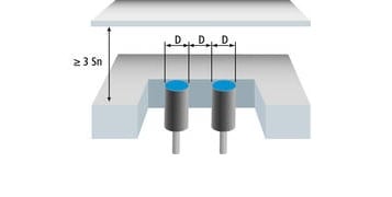
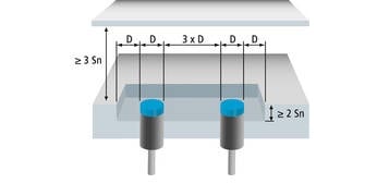
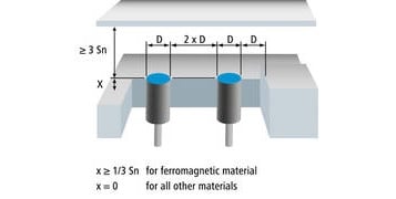
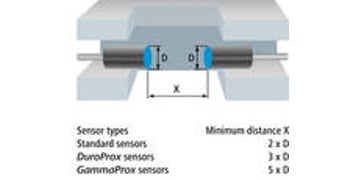
To rule out unintentional interference of the measuring field and to achieve maximum sensing distances, it is required to follow the mounting instructions and to maintain the specified minimum distances. If the minimum distances are undercut, a reduction of the sensing distances is expectable. A sensor test directly at the application is recommended.
Correction factors for different installation situations specified in the sensor data sheet have priority over the general guidelines below.
Maximum installation torque
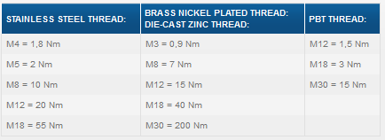
To avoid damage to the proximity switches during mounting, the default torque value should not be exceeded. Reduce torque values by 30 % at the sensor’s face.
Mounting instructions for housings without threads
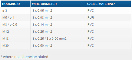
Strong, occasional housing loads, like those which occur e.g. during fixing with headless screws, must be avoided (IFRM 03, 04, 06). Incorrect installation can lead to irreversible damage to the proximity switch. Sensors with a housing diameter of 6.5 mm can be installed optimally with the plastic support bracket 10109474.
Set-up / Teach-In
Baumer Teach-In functions
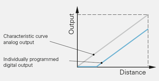
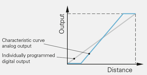
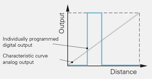
Baumer AlphaProx sensors with linearized characteristic curve, factor 1 sensors and high sensitivity sensors have a teach function with several teach modes. This allows the measuring range to be freely configured within specified limits. If, for example, a small measuring range with a large signal amplitude is required, it is possible to limit this to a few millimeters. The operating direction of the analog output can also be inverted if required.
In addition, the switch-on and switch-off points of a digital output can be defined. These may lie both within and outside the individually programmed measuring range.
Factory Reset
All sensors with teach functions have a factory reset to reset the sensor to the factory settings.
