Typical applications of ultrasonic sensors

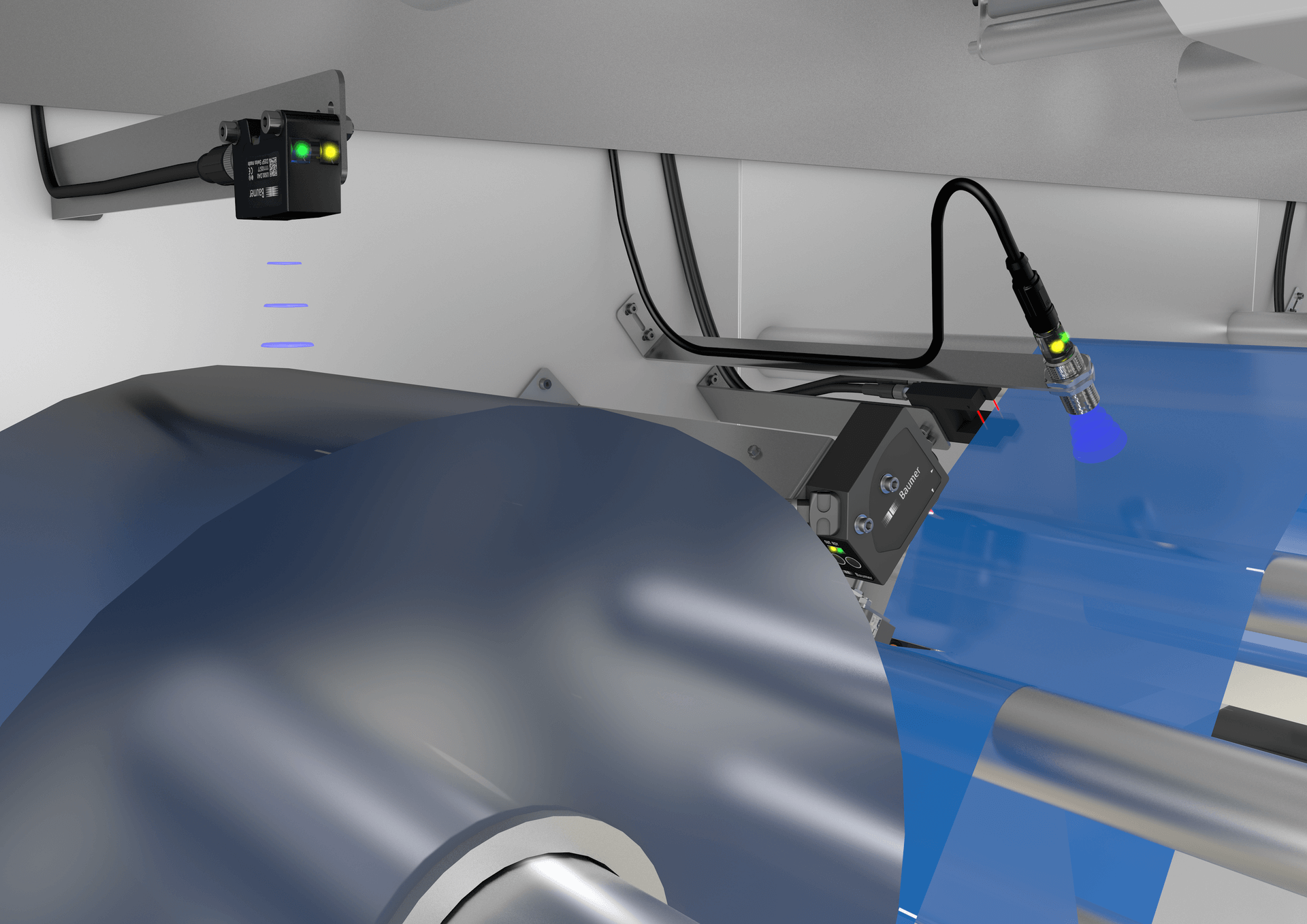
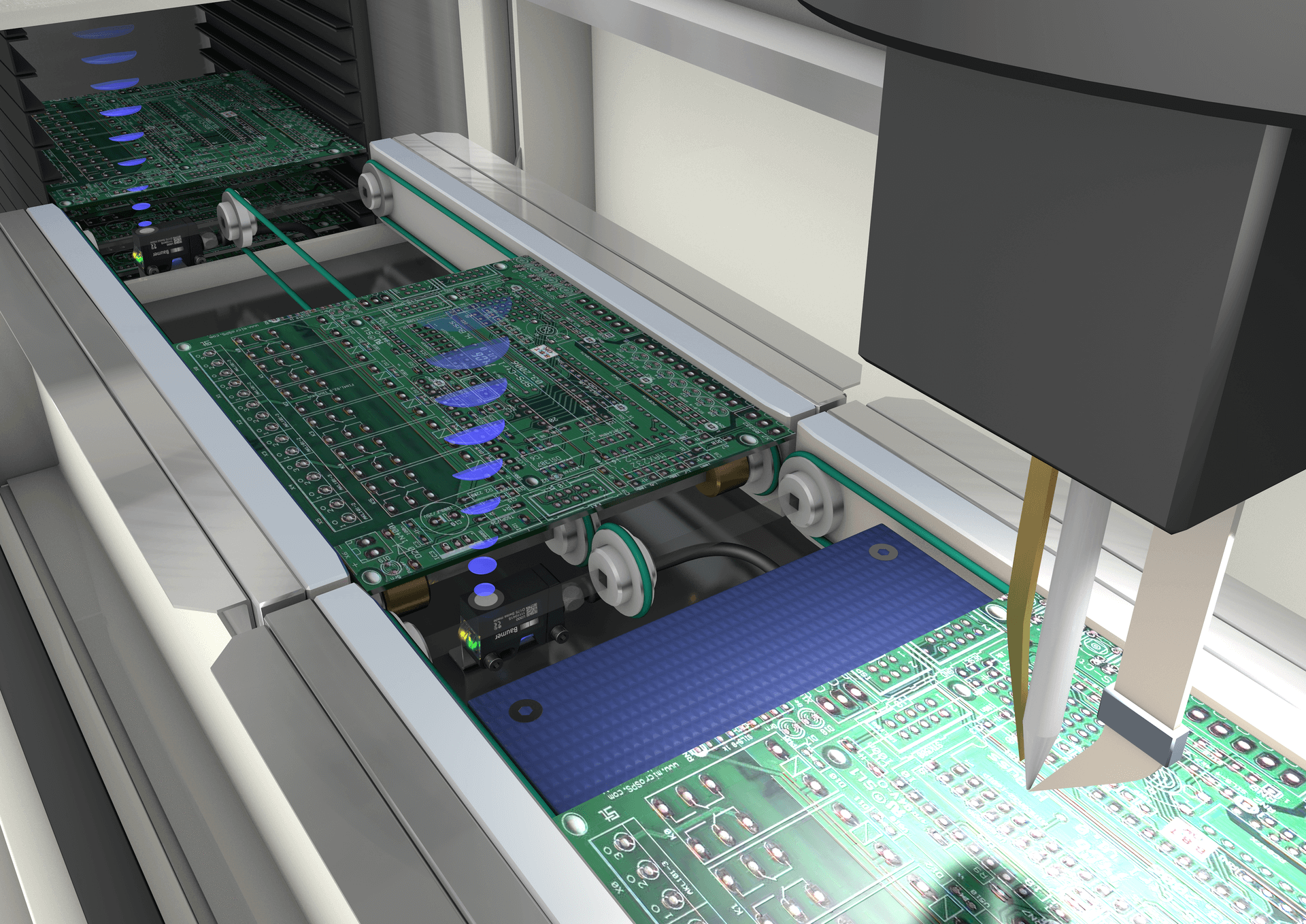
Reliable detection of various carrier materials, no matter which color, whether glossy or transparent.


Ultrasonic sensors reliably measure without contact a distance within the defined range, no matter which object properties and ambient conditions such as the presence of dust. For doing so, an ultrasonic sensor emits high-frequency sound waves and measures the time it takes the waves to hit an object and to reflect back to the sensor (time-of-flight principle). Based on the time measured, the distance between sensor and object is calculated by the speed of sound propagation. In this way, ultrasonic sensors precisely detect the presence and position of objects.
Here you will find our ultrasonic sensors for object detection as well as all ultrasonic distance sensors and ultrasonic level sensors.
The distance is measured by detecting and calculating the time elapsed between ultrasonic wave emission and reception. Distance calculation uses the following formula:
Distance L = (T x C)/2
In this formula, L stands for distance, T for the time between sound wave emission and reception while C is the sound speed. To obtain the distance to the object, the calculated value must be divided by 2, as T is the total time the sound waves require for one travel to and fro.

Most ultrasonic sensors are based on the principle of measuring the propagation time of sound between send and receive (proximity sensor). The barrier principle determines the distance from the sensor to the reflector (retro-reflective sensor) or to an object (through-beam sensor) in the measuring range.
A special sonic transducer is used for the ultrasonic proximity sensors, which allows for alternate transmission and reception of sound waves. The sonic waves emitted by the transducer are reflected by an object and received back in the transducer. After having emitted the sound waves, the ultrasonic sensor will switch to receive mode. The time elapsed between emitting and receiving is proportional to the distance of the object from the sensor.

Sensing is only possible within the detection area. The required sensing range can be adjusted with the sensor's potentiometer or by electronic Teach-in (Teach-in button or remote Teach-in). If an object is detected within the set area, the output will change state which is visualized by the integrated LED.
While sonic waves are best reflected from hard surfaces, targets may also include liquids, granules or powders. In general, ultrasonic sensors are deployed for object detection where optical principles would lack reliability.
In regards to defining the rated sensing range of the sensor, the standard target is a square flat object of one of the following sizes:
The target should be mounted perpendicular to the axis of the sensor.
To ensure reliable object detection, the reflected signal must be strong enough to be read by the sensor. The intensity of the signal depends upon the size of the object to be detected. Using a target of the required minimum size or larger will result in achieving the full scanning distance Sd.
Detection of sound absorbent materials will result in a reduction of the maximum sensing distance. Further, the maximum sensing distance can be achieved as long as the maximum roughness of the object does not exceed 0.2 mm.
The sonic cone profile charts as found in the spec sheets of this catalog represent the active sensing areas for ultrasonic sensors. The charts demonstrate the short-range sonic side lobes, which widen the sensor's close-range aperture angle. Due to sound absorption and air diffusion, the lobes decrease at longer ranges. Size, shape, surface properties and the direction of target detection have very high influence on the lateral detecting region of an ultrasonic sensor. Sonic cone profiles apply to the whole product family, e.g. a 100 - 1000 mm profile is representative for all related sensors of the same sensing range - digital or analog outputs, etc.


Standard square targets made of steel are used to determine the shape of typical sonic cone profiles.
The targets are positioned perpendicularly to the sensor's reference axis, approached sideways at different distances. The sonic cone profile is then plotted by connecting the measured points with a line. The cone shape can vary if round or differently shaped objects are detected.
The retro-reflective ultrasonic sensor is similar in operation to the proximity sensor version. The distance from the sensor to a reflector or to a target within the sensing distance is determined by measuring the propagation time. Any sound reflecting, stationary object can be used as a reflector. The sensing distance of the sensor (Sd; distance from sensor to reflector) can be adjusted by the sensor’s potentiometer or via IO-Link (if the sensor has this feature). As long as the measured propagation time of the ultrasonic signal corresponds to the distance from the sensor to the reflector, the output of the sensor is in it’s non-active state. When a target enters the sensing range and changes the sonic wave propagation time, the sensor changes its output state. This allows for detection of most materials including sound absorbing objects.

The standard target is defined as a square, level object with an edge length of 30 mm (Sde > 1000 mm: 100 mm edge length, Sde ≥ 2500 mm: 300 mm edge length) which is perpendicular to the sensor reference axis. The reflector must be made of a material with good sound reflection properties and be at least the same size as the target.

In this scenario, the emitter and receiver are in separate housings. The emitter produces a continuous sound wave that is picked up by the receiver. An object interrupting the sonic beam will make the receiver react and will cause it to change it’s output state.
With the help of a built-in potentiometer or IO-Link (if available), the user can adjust the strength of the transmitted sound wave.
The state of the output stage as well as the signal intensity are indicated by an LED.

The sonic beam angle (α) defines the boundaries of the emitted conical beam of the ultrasonic through-beam sensor.
Due to the narrow angle of the sonic beam the repeatability of the switching point of two successive targets, under identical conditions, is better than 3 mm.
Hysteresis is the difference between the operating point (S1) and the release point (S2). If an object interrupts the sonic beam, the signal level must be increased by about 75 % in order to reset the output signal. Objects which follow one another in quick succession can therefore be easily detected.


Ultrasonic sensors are multifaceted in the world of sensors and are suitable for virtually any detection or measurement tasks in industrial applications. The objects to be detected can be solid, liquid, granular or in powder form. They reliably detect transparent or high gloss objects as well as objects of changing color. Being extremely tolerant to dirt, the efficiency of ultrasonic sensors comes into its own especially in harsh working environments, as process reliability is not adversely affected by dust, smoke, mist or similar.
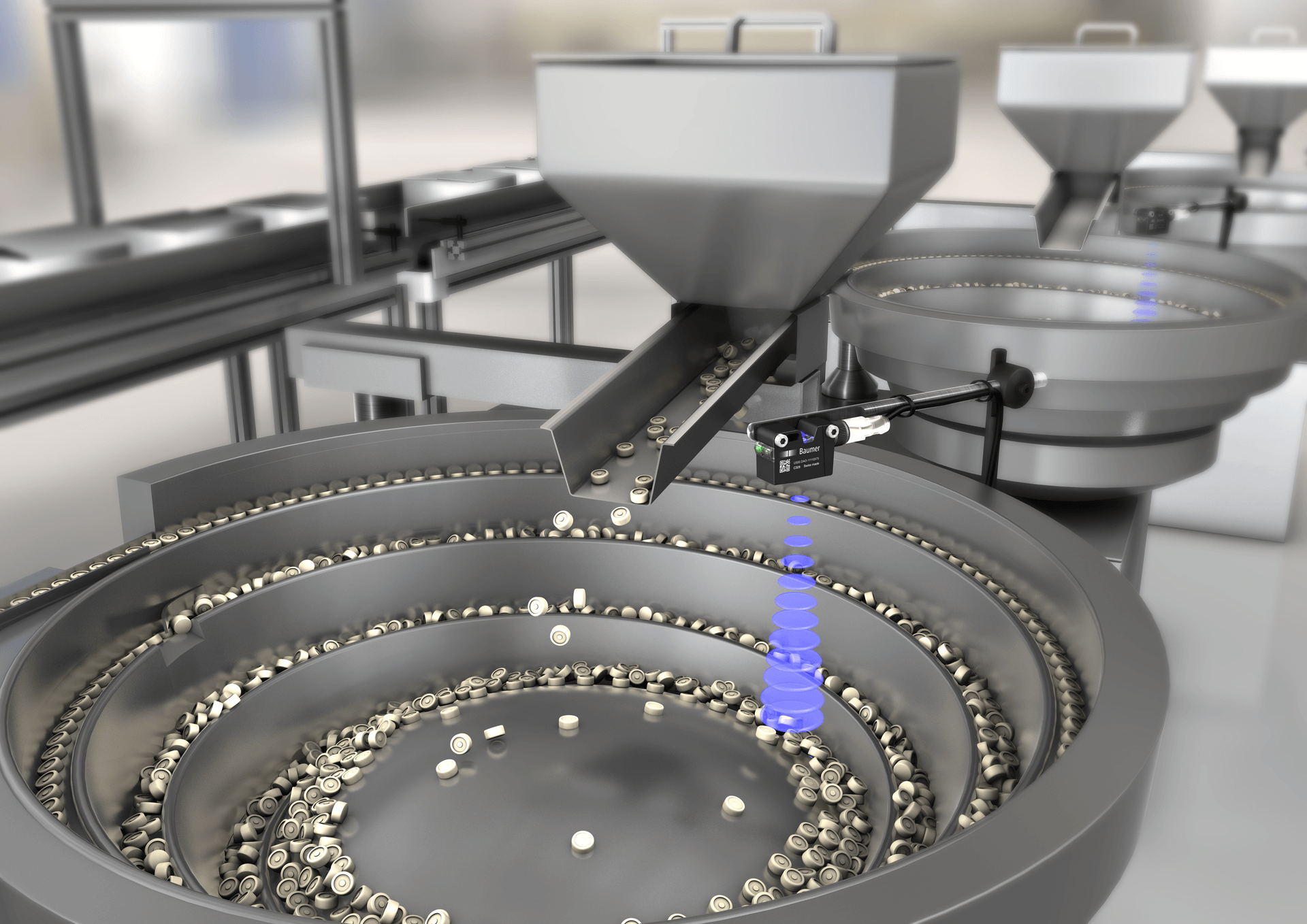
Thanks to their application versatility, ultrasonic sensors are used in most varied industries, such as packaging, electronics and feeder technology. Here you find more application examples of ultrasonic sensors and specific application benefits in specific applications.
Typical applications of ultrasonic sensors

Reliable detection of various carrier materials, no matter which color, whether glossy or transparent.


For optimal results in parallel operation of several ultrasonic sensors please consider the following to avoid sensing errors by mutual interference: