What is an inductive sensor?
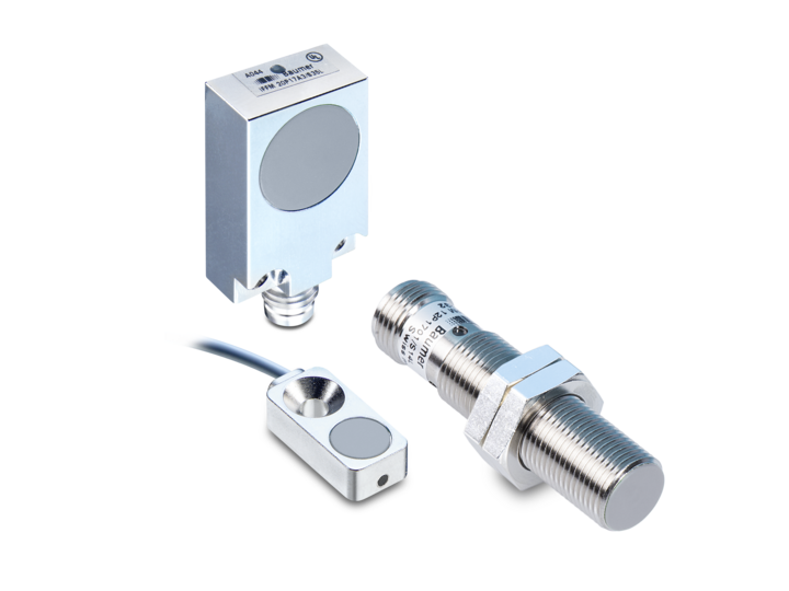
An inductive sensor is a non-contact sensor for detecting metallic objects. Inductive sensors are commonly used in industrial applications to determine and monitor metallic objects regarding position, movement or distances.
Types of inductive sensors comprise inductive proximity sensors and inductive distance sensors, which detect close metallic objects using the inductive measuring principle. Inductive proximity sensors detect the presence of a metallic object and generate a switching signal. Inductive distance sensors measure the distance to metallic objects by changes in the voltage induced.
Here you will find all our inductive proximity sensors and our inductive distance sensors:


How does an inductive sensor work?
Design of inductive sensors
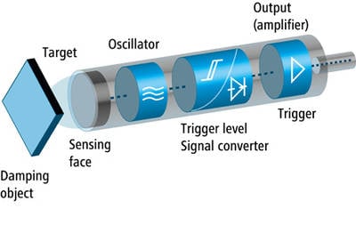
Inductive proximity sensors and distance sensors comprise several components:
- Attenuation object: The metallic object to be detected.
- Measurement field: The sensor-generated electromagnetic field.
- Active sensor surface: The sensor surface emitting the electromagnetic field.
- Oscillator: A circuit generating high-frequency alternating voltage signals which build the measurement field.
- Trigger stage / signal converter: Electronic system that detects the changes in the oscillator signal caused by presence of the damping object and convert it into analog or digital signals.
- Output amplifier: Amplifies the converted signal for output to external devices.
Switching distance of inductive sensors
Standardized calibrating plate
The standardized calibrating metal plate is used for calibrating and testing inductive sensors. It is of square shape, 1 mm thick and made of Fe 360 (ST 37). The side length corresponds to either the diameter of the active sensor surface or three times the nominal operating distance Sn, whichever is greater. The standardized calibrating plate ensures measuring and comparing of sensor characteristics under standardized conditions.
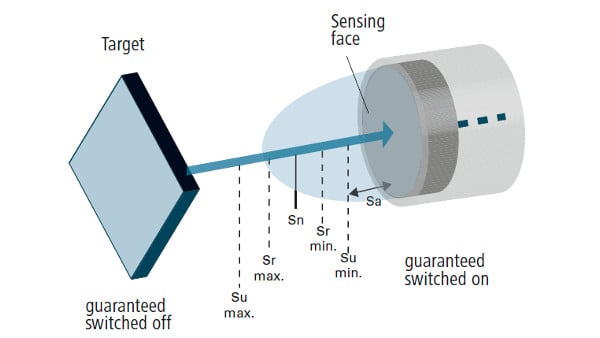
Nominal operating distance Sn
The nominal operating distance Sn is the distance at which the sensor will output a switching signal when having detected a metallic object under ideal conditions (e.g. using a standardized calibrating plate). The nominal operating distance is defined at sensor manufacture and specifies the switching distance at which in theory the sensor should detect the object. It does not take into account manufacturing tolerances or change by external influences such as voltage and temperature.
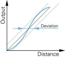
Real operating distance Sr
The real operating distance is the true measured distance at which the sensor would detect a metallic object in a specific application under specific installation conditions and at a specified temperature and voltage. The real operating distance may slightly differ from the nominal operating distance due to general and manufacturing tolerances. For inductive proximity sensors, it has to be between 90% and 110% of the rated switching distance at 23 ±5 °C.
Usable operating distance Su
The usable operating distance Su describes the real operating distance range in which the sensor is reliably operating. Variables such as temperature, voltage drops and mechanical tolerances are taken into account. The operating distance of a single proximity sensor is measured throughout the entire operating temperature range at supply voltage between 90 % and 110 % of the nominal value.
Safe operating distance Sa
The assured operating distance Sa is the distance up to which the sensor would reliably provide assured switching signals, regardless of ambient conditions such as temperature, voltage and manufacturing tolerances. With inductive proximity sensors, the assured operating distance is between 0 % and 81 % of the rated operating distance. This is the most conservative value ensuring reliable sensor switching operations under any condition.
Correction factor cf
The operating distance of inductive sensors depends on the properties of the metallic material to be measured. If metallic materials other than the standardized calibrating plate (Fe 360) are used for damping, the specified operating distance must be multiplied by the material correction factor specified in the data sheet. These results are to be considered as guidelines. Please note that object geometries that deviate from the standardized calibrating plate will also have an influence on the operating distance. Should the data sheet not specify any correction factors you may use the standard values of the table below.
| Material | Correction factor (cf) |
| Steel | 1 |
| Copper | 0,25 ... 0,45 |
| Brass | 0,35 ... 0,50 |
| Aluminium | 0,30 ... 0,45 |
| Stainless steel | 0,60 ... 1,00 |
| Nickel | 0,65 ... 0,75 |
| Cast iron | 0,90 ... 1,05 |
Detection on aluminum foils or metal-coated materials may achieve an operating distance similar to that of steel. The nominal operating distance Sn depends on layer composition and thickness.
With standard sensors, the operating distance is reduced by up to 70% on non-ferromagnetic metals. Inductive factor 1 sensors integrate a microcontroller compensating such influence. This way, factor 1 sensors do not provide any material-dependent reduction factor. For this reason these sensors are ideal for measurements on aluminum or non-ferrous metals since they achieve a larger operating distance.
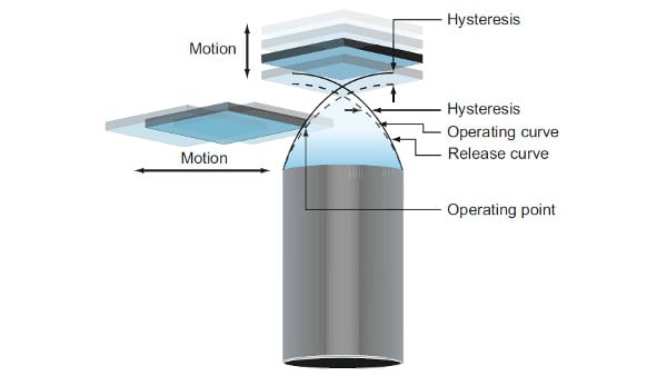
Switching hysteresis
Hysteresis means the difference between switch-on and switch-off as the calibrating plate is approaching and moving away from the initiator. It ensures stable operation of inductive sensors and prevents switching errors in the presence of mechanical vibrations.
Switching frequency and speed measurement
The switching frequency according to the measuring method compliant to EN 60947-5-2 is the maximum possible number of switching operations per second. The true switching frequency achieved also depends on certain properties of the component to be detected, such as size or material. The high switching frequencies of inductive sensors, typically up to 5 kHz, allow for fast applications and precise detection of motion.
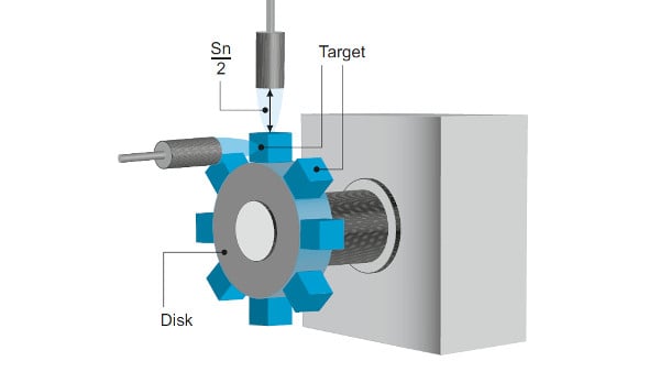
Speed measurement with inductive sensors is a precise method for monitoring or accurately determining the speed of a rotating object. The sensor is mounted close to the rotating shaft or the rotating gear wheel. Detection of metallic structures with electromagnetic fields would generate electrical pulses that are being counted. The speed in revolutions per minute is calculated from the pulse switching frequency.
Inductive sensors applications
Difference between inductive and capacitive sensors
Inductive sensors only detect metal, while capacitive sensors also detect non-conductive materials such as glass, liquids and plastics. Operation of both is non-contact: Inductive sensors use magnetic fields under influence of metallic objects, while capacitive sensors measure changes in electrical fields caused by the dielectric constant of different materials.
Here you will find all our capacitive sensors
Advantages of inductive sensors
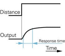
Thanks to their small design, inductive sensors fit easily into tight spots for maximum use of space. By virtue of their fast response time they are ideal for applications requiring precise and fast detection. Further they do not contain any moving parts for reduced maintenance costs and increased service life. This way, inductive sensors are ideal for multifaceted applications in varied industries.
Further product benefits on our product pages inductive proximity sensors and inductive distance sensors.
Installation and electrical connection of inductive sensors
Proper installation is crucial for reliable inductive sensor function. Find out more about commissioning, installation and setting options. Furthermore, there is more information on the different output types (e.g. PNP or NPN output) and corresponding connection diagrams.