Die Leitfähigkeitsmessgeräte von Baumer dienen zur Medientrennung und -analyse in Anwendungen der Nahrungsmittel- und Getränkeindustrie sowie in der Wasseraufbereitungstechnik. Sie bieten einzigartige Vorteile bezüglich Genauigkeit und Anzeigeoptionen.
Funktionsprinzip eines induktiven Leitfähigkeitssensors Baumer AFI
Abgrenzung zwischen konduktiver und induktiver Technologie
Der klassische Aufbau von konduktiven Leitfähigkeitssensoren, deren Elektroden galvanisch in Kontakt mit dem zu messenden Medium stehen, hat seine Grenzen dort, wo es durch hohe Ionenkonzentrationen zum sog. Polarisierungseffekt kommen kann. Dieser wirkt quasi wie ein zusätzlicher Widerstand und verfälscht damit das Messergebnis. Ebenso können Ablagerungen (z. B. Laugenstein) isolierende Schichten aufbauen, die eine konduktive Leitfähigkeitsmessung gänzlich unmöglich machen.
Bei Applikationen mit hohen Ionenkonzentrationen, wie z. B. mit Laugen und Säuren mit Leitfähigkeitswerten in der Grössenordnung von 100 mS/cm, und bei Gefahr von Ablagerungen bietet die induktive Technologie die einzige zuverlässige Leitfähigkeitsmessung und damit sichere Steuerung von Prozessen. Für die Messung sehr kleiner Leitfähigkeitswerte ist das induktive Messprinzip dagegen nicht geeignet. Der kleinste Messbereich beträgt 500 µS/cm (0.5 mS/cm); damit lassen sich noch genaue Messungen in der Grössenordnung um 50 µS/cm durchführen.
Aufbau des induktiven Leitfähigkeitssensors AFI
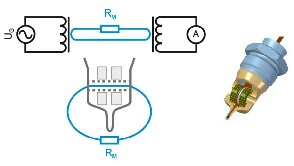
The sensor element with a seamless PEEK housing contains two ring core coils that act as two virtual transformers arranged in series. The first primary winding is fed by an oscillator in the kilohertz range. The liquid loop that is created by the current measuring passage through the interior of the two ring core coils and the surrounding area connects the secondary side of the first transformer to the primary side of the second transformer. This connection can be considered a common winding of both transformers. The secondary winding of the second transformer is connected to a galvanometer. The volume of the liquid resistance RM results in an associated current measurement value. Using a simple calculation rule (Ohm’s law), this value together with the known oscillator voltage UG is transformed into the conductance value GM to be output.
The sensitivity of the galvanometer must be adjusted for different conductance value ranges. The user can do this by setting freely defined measurement ranges that can be selected during operation by activating control inputs.
The inductive measurement principle is not reliant on the movement of liquids in the current measuring passage. Nevertheless, it is recommend to align the channel in the direction of the flow to achieve better cleaning results. The symmetrical design of the channel accommodates both flow directions without the risk of clogging by media components.
A precise and highly responsive Pt100 temperature sensor is integrated into the tip of the sensor element. The temperature of the medium measured by this is available as a measuring signal and is used in addition to the physical temperature compensation of the raw conductivity value.
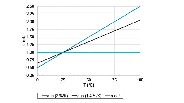
Temperature compensation
The conductivity of a liquid generally depends on the temperature. For many aqueous solutions, it increases at +2%/K. To be able to compare measurements, measuring devices refer the directly determined conductivity back to a reference temperature. This is usually defined as 25 °C. In addition to this definition, the AFI also allows the input of a temperature coefficient in %/K. This must be set to 0%/K if temperature compensation is to be dispensed with. Non-linear temperature coefficients can be specified with an additional quadratic element.