A
Ausgangssignal
Art des Ausgangssignal des Sensors mit elektrischem Verstärker. Das Ausgangssignal ist proportional zur Nennkraft. Bei einem 100 N Kraftsensor mit Spannungsausgang 0 – 10 V, entsprechen 0 V 0 N und 10 V einer Nennkraft von 100 N.
B
Betriebsspannungsbereich
In diesem Spannungsbereich kann der Sensor dauerhaft über den gesamten Betriebstemperaturbereich betrieben werden ohne das die Grenzen der messtechnischen Eigenschaften überschritten werden und es zu einer Beeinträchtigung der elektrischen Schutzschaltung kommt.
Betriebstemperaturbereich
Der Betriebstemperaturbereich beschreibt den Temperaturbereich, in dem der Sensor die messtechnischen Eigenschaften einhält.
Brücken - Ausgangswiderstand
Ohmscher Widerstand zwischen den Signalausgängen Sig+ und Sig- eines passiven Messaufnehmer.
Brücken - Eingangswiderstand
Ohmscher Widerstand zwischen den Versorgungsanschlüssen +VS und -VS eines passiven Messaufnehmer.
Brückenspannung
Stabilisierte Versorgungsspannung für den passiven Messaufnehmer.
Brückenwiderstand
Ohmscher Widerstand der gesamten Messbrücke.
Bürde
Maximaler Lastwiderstand eines Stromausgangs. Die Bürde ist der Messwiderstand (Eingangswiderstand der analogen Messkarte) um den Signalstrom in eine messbare Spannung umzuwandeln.
D
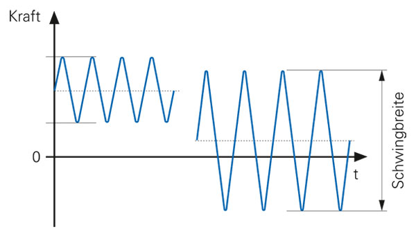
Dauerfestigkeit
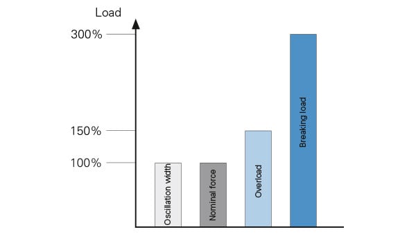
Auf die Nennkraft bezogene Belastungsgrenze, bis zu der der Sensor mindestens über 1 Million dynamische Belastungszyklen ohne bleibende Veränderungen der messtechnischen Eigenschaften erfahren kann. In der Literatur auch oft unter dem Begriff der relativen Schwingbreite zu finden.
E
EMV
Richtlinie / Norm über Störfestigkeit, elektromagnetische Emissionen und Einstrahlungen.
G
Grenzbiegemoment
Zulässiges statisches Biegemoment, das bei gleichzeitiger Belastung mit Nennkraft keine bleibenden signifikanten Veränderungen der messtechnischen Eigenschaften des Kraftsensors bewirkt.
Grenzdrehmoment
Zulässiges Drehmoment um die Messachse des Kraftsensors, das bei gleichzeitiger Belastung mit Nennkraft keine bleibenden signifikanten Veränderungen der messtechnischen Eigenschaften des Kraftsensors bewirkt.
Grenzfrequenz
Bei dieser Frequenz wird das Ausgangssignal um 3dB (auf rund 70.7%) gedämpft.
Grenzquerkraft
Zulässige statische Querkraft, die bei gleichzeitiger Belastung mit Nennkraft keine bleibenden signifikanten Veränderungen der messtechnischen Eigenschaften des Kraftsensors bewirkt.
Fundamental resonant frequency
Resonant frequency with which the unloaded force sensor parts, without force introduction, oscillates after shock-like excitation in the direction of the measuring axis, its base provided for securing it being coupled to an adequate mass.
H
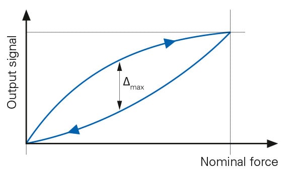
Hysteresis
Hysteresis, or also known in the literature as hysteresis error, is the difference between the output signals of an up and down series under the same load, relative to the output signal under increasing load, under ideal installation conditions. Influencing factors are the material hysteresis of the sensor body, the hysteresis in the measuring principle as well as external frictional influences caused by the measuring setup.
I
Insulation resistance
Ohmic resistance, measured between any connecting cable and the sensor body under a defined test voltage.
K
Corrosion protection
Corrosion protection describes the corrosion category in DIN EN ISO 12944-2 according to which the sensor can be used without problems under certain ambient conditions.
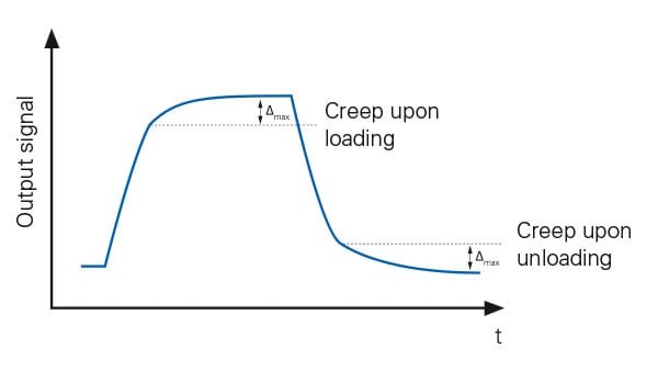
Creep error
Creep describes the time-dependent change in the output signal of the force sensor under constant load. A distinction is made between loading creep and unloading creep. In loading creep, the change in the measuring signal is examined at constant force over a longer period of time. In unloading creep, the force sensor is first loaded with a constant nominal force. After unloading, the change in the measuring signal is then evaluated in an unloaded state.
Sensitivity tolerance
Relative deviation of sensitivity under nominal load from nominal sensitivity.
L
Load resistance
Minimum input resistance of the connected measuring system.
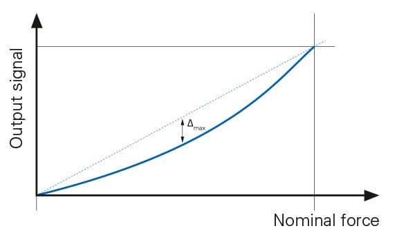
Non-linearity
Non-linearity is the maximum deviation of the calibration curve of a sensor, determined with increasing force from the reference line through the zero point, under ideal installation conditions. The reference line is a compensation function of the first degree, the slope of which is determined in such a way that the sum of the squares of all signal deviations from the reference line results in a minimum (in literature: weighted least squares method). The main cause of non-linearity is often a non-symmetrical introduction of force.
Storage temperature range
Temperature range in which the sensor can be stored without mechanical or electrical stress, without any permanent significant changes in its physical properties being detectable when the sensor is reused within the operating temperature range.
M
Measuring rate
The measuring rate describes the internal sampling rate of the analog sensor signal.
Measuring resolution
Smallest possible subdivision of transferable measured values in digital systems.
Minimum breaking force
The minimum breaking force describes the force of the force sensor above which mechanical destruction is to be expected. If the load exceeds the minimum breaking force, further use of the sensor is no longer recommended.
N
Nominal force
Nominal force is the force for which the sensor is nominally designed, i.e. up to which the metrological specifications are complied with. Depending on the type, a distinction can be made between tensile and nominal compression force. In the following specifications, the percentage always refers to the nominal force.
Nominal measuring path
The nominal measuring path describes the path that the two external force introduction points or surfaces of the force sensor take relative to each other in the measuring direction as a result of a load with nominal force. The typical nominal measuring path for diaphragm force sensors is approx. 0.1 mm.
Nominal sensitivity
Ratiometric output signal of a passive sensor at nominal force. The output signal is proportional to the bridge voltage \(U_{E}\) .
Nominal strain
Nominal strain is the strain for which the sensor is nominally designed, i.e. up to which the metrological specifications are complied with. In the following specifications, the percentage always refers to the nominal strain.
Zero point deviation
The zero point deviation describes the maximum deviation of the zero signal in a disassembled state from the value zero in relation to nominal sensitivity. With force sensors below 100 N, it is important to ensure that the sensor lies on a flat surface without force.
R
Noise
Effective value of the noise of the output signal in the specified frequency range.
Random DIN EN 60068-2-64
Resistance of the sensor to vibration, without the sensor experiencing any permanent significant changes in its metrological properties up to nominal force.
Reproducibility
Reproducibility describes the accuracy of the sensor when the installation position is changed. The maximum difference between the output signals with the same force is determined from several measurement series in different installation positions. Reproducibility is particularly important for force sensors that measure temporarily and are installed and removed frequently.
S
Current consumption
The maximum current consumption under nominal conditions; the starting current may be higher for a few ms.
Protection class DIN EN 60529
The protection class indicates to what extent the sensor is protected against moisture and dust as well as the ingress of foreign bodies.
Sensor stiffness
Sensor stiffness is defined as the ratio of force to axial deformation of the sensor body. The fundamental resonant frequency of the sensor can be decisively influenced with the help of sensor stiffness.
Shock DIN EN 60068-2-27
Resistance of the sensor to impacts (mechanical shocks), without the sensor experiencing any permanent significant changes in its metrological properties up to nominal force.
Signal polarity positive
Positive change in the output signal with defined direction of the input parameter.
T
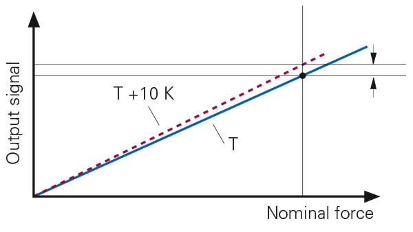
Temperature effect sensitivity
\(TK_{E}\) describes the relative change in the sensitivity of the force sensor as a result of the change in the ambient temperature \(T_{i}\) of 10 K. This information is given in % per 10 K.
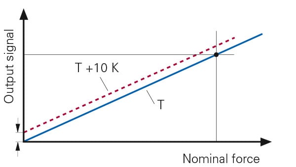
Temperature effect zero
\(TK_{0}\) describes the change of the zero signal of the force sensor related to the nominal sensitivity due to a change in the ambient temperature \(T_{i}\) of 10 K. This information is given in % per 10 K.
Zero adjustment active
At least this voltage must be applied to the zero adjustment input so that zero adjustment can be reliably started.
Zero adjustment inactive
This voltage must not be exceeded at the zero adjustment input to reliably ensure that no zero adjustment is started.
Zero adjustment pulse
The zero adjustment pulse is the minimum time in which \(U_{Ta}\) must be exceeded to start zero adjustment.
Zero adjustment range
Within this range, the sensor is able to carry out zero adjustment and adjust the output signal to the zero signal.
Zero adjustment time
This is the maximum time the sensor needs to perform zero adjustment.
Ü
Overload
Overload is the force up to which the force sensor remains fully functional under a single load and continues to comply with the technical specifications. The sensor does not undergo any plastic deformation.
V
Vibration DIN EN 60068-2-6
Resistance of the sensor to forced sinusoidal oscillatory movements with a specified degree of severity, without permanent significant changes in its metrological properties being detectable up to nominal force.
W
Repeatability
Repeatability describes the accuracy of the sensor when the installation position is not changed. The maximum difference between the output signals with the same force is determined from several measurement series when the installation position is not changed. Repeatability is particularly important for force sensors that are installed only once.